Testing the Limits: Ensuring PeakSat's Components can Endure the Harsh Reality of Space
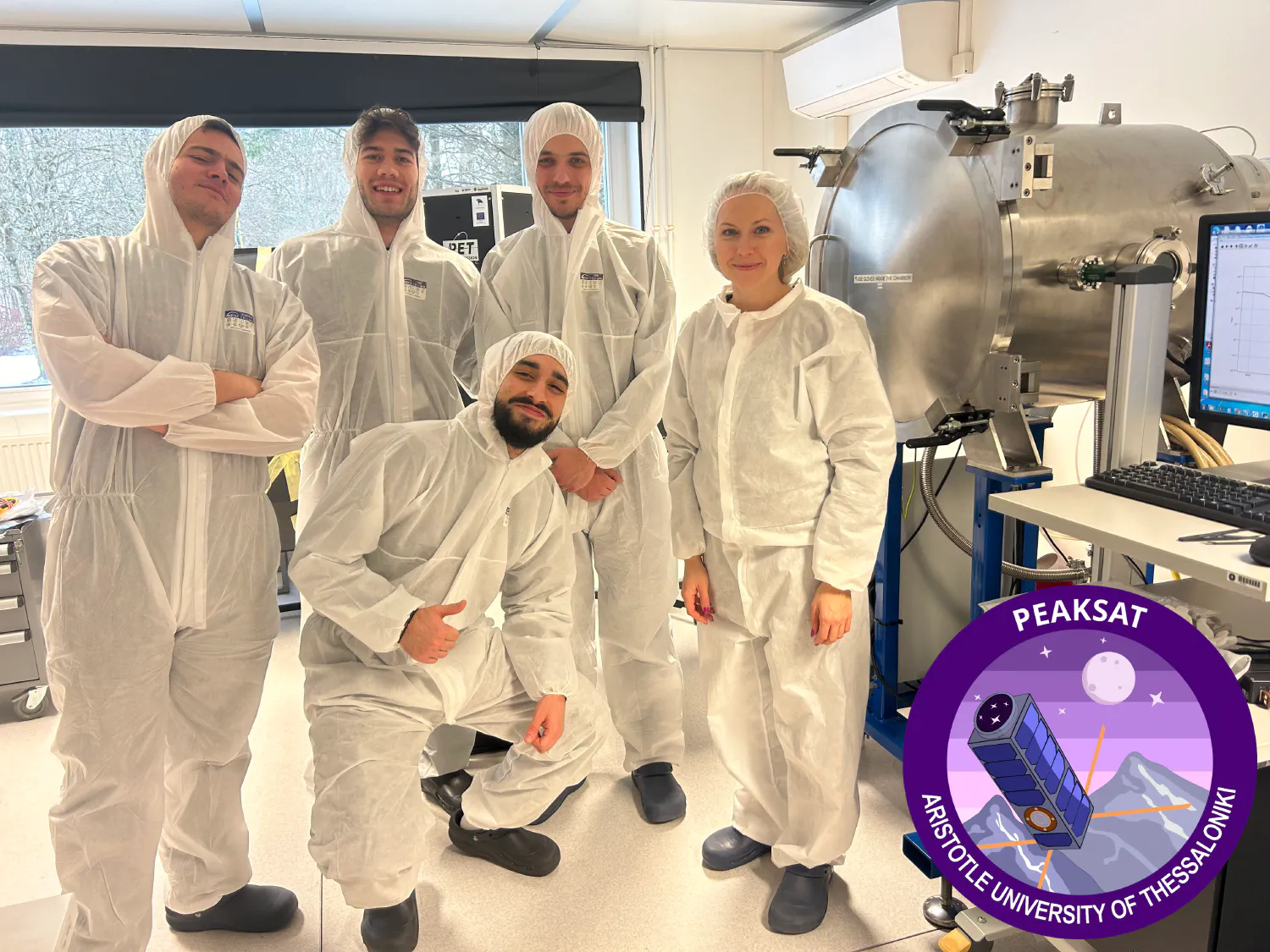
Recently, the PeakSat team embarked on a mission to Tõravere, Estonia, to conduct a Qualification Testing Campaign on the in-house constructed components of our PeakSat nanosatellite. Setting out from Thessaloniki were Vasileios-Panagiotis Moustakas, Systems Engineer; Dimitris Sourlantzis, Software Team Lead; Andronikos Kostas, Communications Engineer; and Ioannis Tatsoglou, Hardware and Software Engineer. Our mission? To ensure these crucial components are robust enough to withstand the harsh environment of outer space.
Introducing PeakSat
PeakSat is a 3-unit nanosatellite designed to demonstrate the capability of performing optical links with Optical Ground Stations in Greece. As of April 2024, it is under design by a consortium including the Aristotle University of Thessaloniki and Prisma Electronics SA. Composed of Commercial Off-The-Shelf (COTS) components, in-house developed subsystems and an optical terminal as a payload, PeakSat is aiming to advance optical communications and pave the way for a space-based optical communications network. PeakSat is part of the Greek CubeSats In-Orbit Validation Projects program coordinated by the European Space Agency, with the support of the Ministry of Digital Governance and is funded by the European Union - NextGenerationEU.
Testing Focus: Critical Components and Simulated Space Conditions
Our focus for this qualification campaign was on two mission-critical parts of the PeakSat platform: the Communications board and the On-Board Computer (OBC) board. Our Communications board is based on the SatNOGS-COMMS project by the Libre Space Foundation, while the OBC board is based on the one developed by our sister project, AcubeSAT. Alongside these components, we stacked an electromagnetically insulating shield (EMI shield), which ensures that no electromagnetic radiation interferes with the function of the boards.
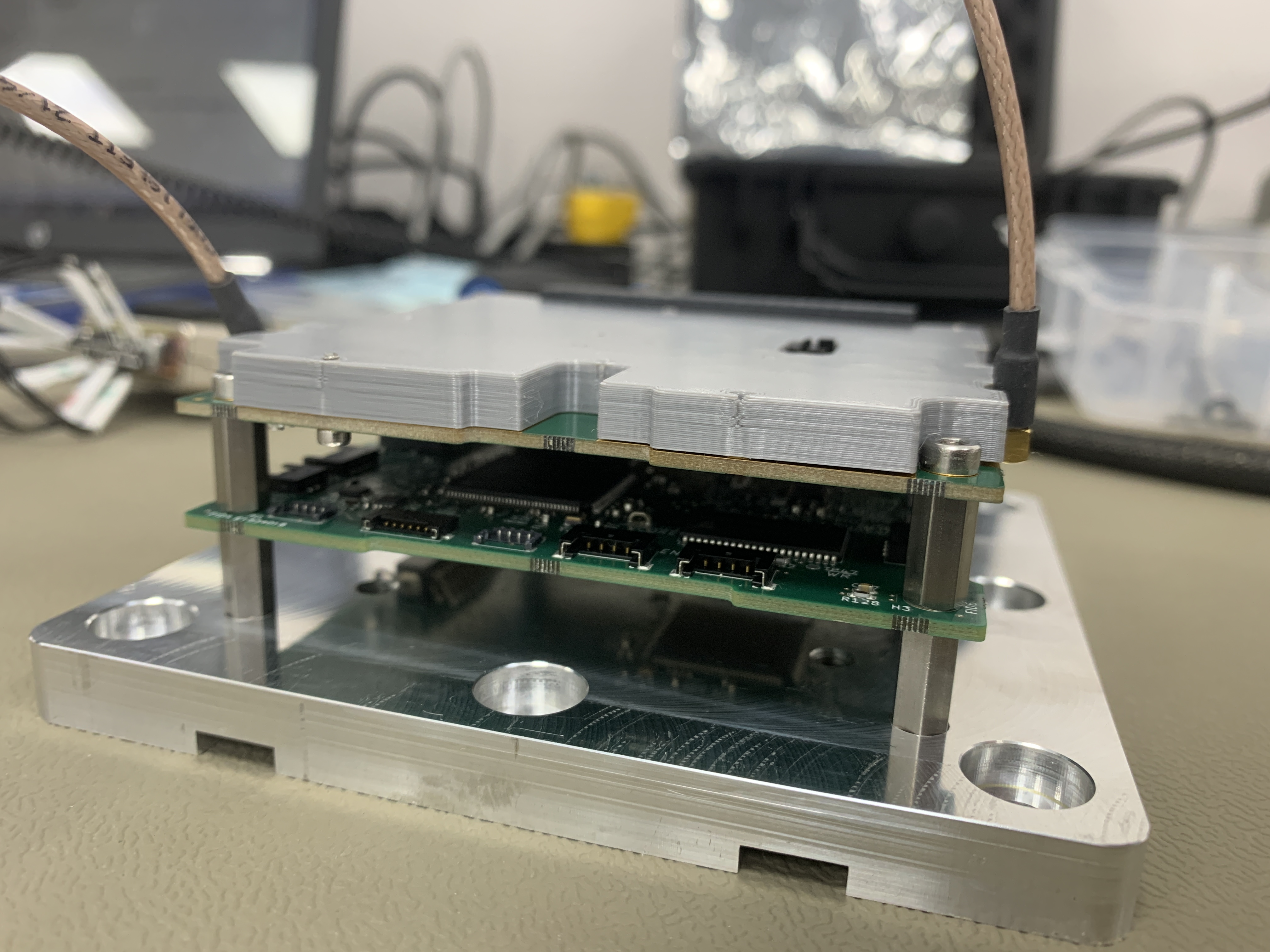
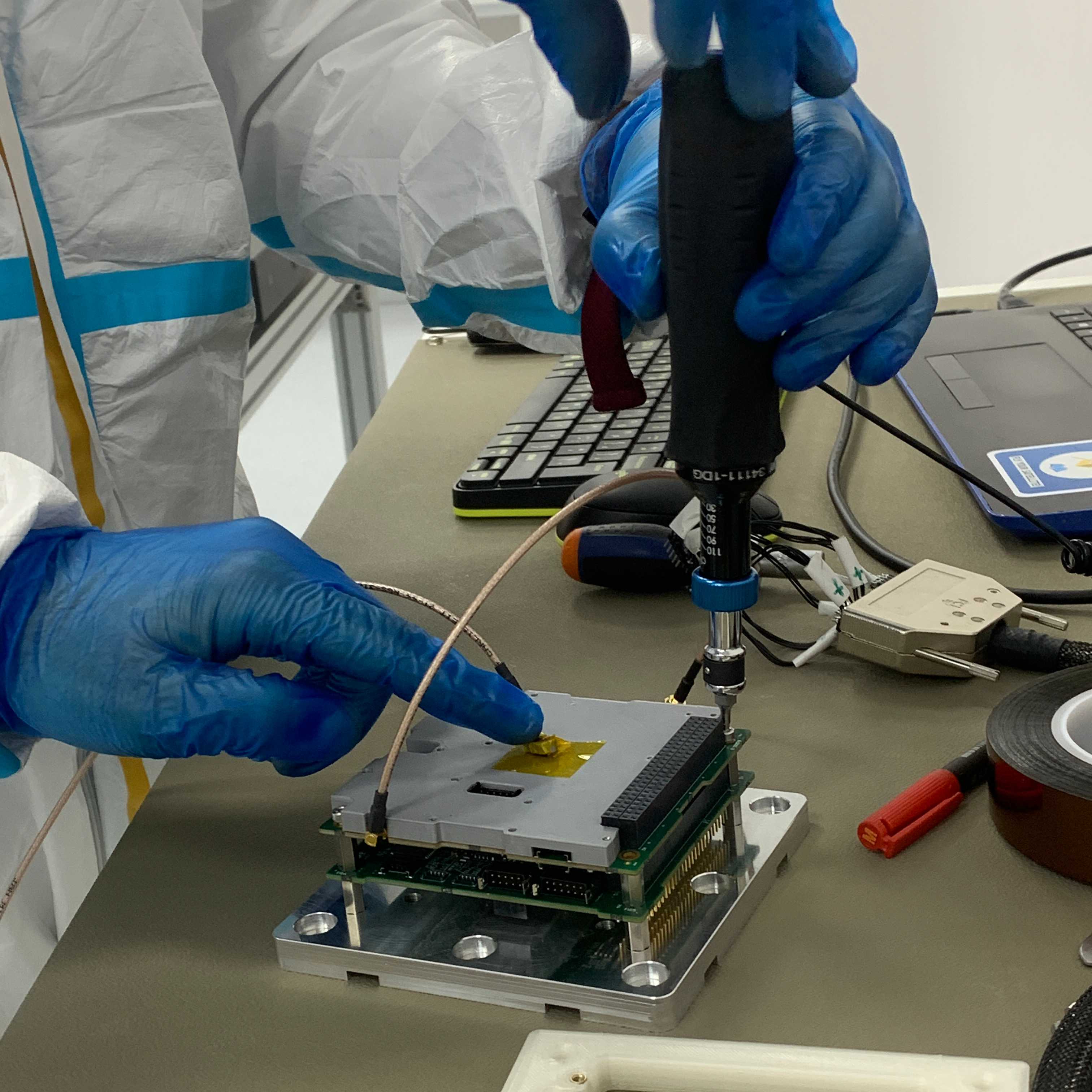
The PCB assembly
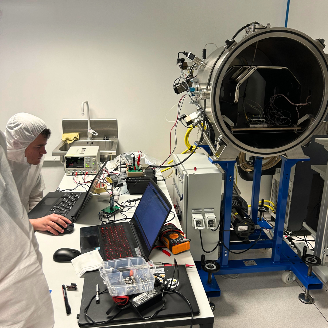
Our testing journey began in our cleanroom facilities, in KEDEK/AUTh, where we completed ambient functional tests of the subsystems under Earth-like conditions. Specifically, we subjected them to high temperatures under atmospheric pressure. Once they passed these initial tests, we proceeded to the next phase: the campaign tests at Tartu Observatory facilities.
At Tartu Observatory, we simulated the extreme conditions of the launch and space with the Vibration (VIBE) and Thermal Vacuum Chamber (TVAC) tests, following the ECSS-E-ST-10-03 testing standard, and adhering to the principle of “Test as You Fly and Fly as You Test.”
The Principle of Simulating Test and Orbit Conditions
This principle emphasizes the importance of replicating the conditions and environments that a satellite will encounter during its mission as closely as possible during the testing phase, so that no unexpected changes between ground and space lead to incorrect behavior.
In more detail:
-
“Test as You Fly”: This aspect emphasizes conducting tests on satellite components and systems under conditions that simulate the actual operational environment they will experience. This includes subjecting them to factors such as vibration, extreme temperature, high vacuum conditions, but also testing under a realistic mission scenario and verifying all functionality of the components.
-
“Fly as You Test”: Once a satellite component or system has been thoroughly tested and validated under all these different conditions, this principle states that it should then be used in the actual mission exactly as it was tested. This ensures that there are no discrepancies between the performance of the component or system during testing and its behavior during the mission itself.
Testing Procedures and Outcomes: Addressing Challenges
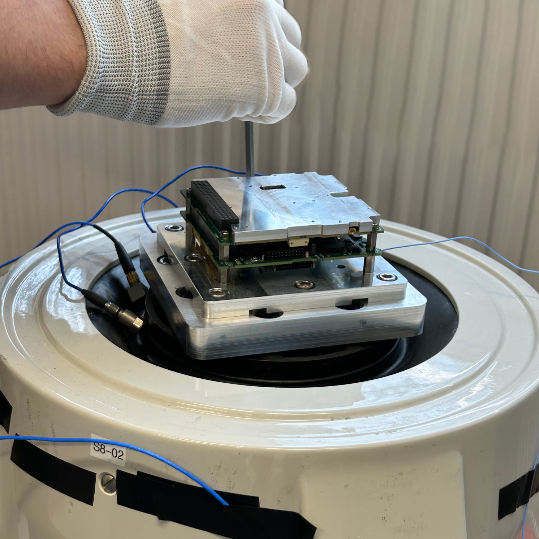
The Boards and EMI shield on the shaker for the Vibrations test.
During Vibration testing, the PCB assembly undergoes controlled mechanical vibrations along different axes to simulate the harsh conditions of launch and space operations. These vibrations are applied according to predefined test profiles that specify the frequency range, amplitude, and duration. Throughout the test, accelerometers and other sensors monitor parameters like acceleration and displacement, providing valuable data for analysis. After completion, the collected data is thoroughly evaluated to assess the boards' performance, including any structural damage or electrical issues. The entire test process, including set-up, execution, and teardown, spanned one day.
During testing, we encountered an issue in the x-axis when two screws from the setup unexpectedly dislodged.
Then we conducted a repeat test; however, the outcome remained inconclusive due to the unavailability of the anticipated accelerometer measurements, hindering our ability to determine its success and prompting a further investigation. Upon disassembling the EMI shield from the board, we discovered that a spacer, initially secured by the two screws, had shifted out of position, which was the root cause for the shift in frequencies observed after modal surveys. Upon closer inspection, it became evident that the screws had loosened due to improper manufacturing specifications of the EMI shield
Fortunately, functional testing after the Vibration test showed that the PCB assembly survived the mechanical stress throughout the test, demonstrating their ability to withstand intense vibrations. However, the results of the test highlighted the necessity for a more robust and detailed design solution for the mounting of the EMI shield.
Next came the TVAC test which lasted 4 days. The first day of the test, we prepared the TVAC set up which consisted of placing the Device Under Test (DUT) inside the TVAC, piece by piece, while placing temperature sensors in between each component.
During the TVAC test, we exposed the components to the extreme temperatures and vacuum conditions of space, while constantly monitoring their behavior and outputs. Conducting four cycles of temperature variations over 4 days, ranging from -21°C to +60°C, we encountered some challenges.
The first cycle was “non-operational”, meaning that the boards were subjected to even harsher temperatures, but were powered on momentarily (for 3 to 5 seconds), aiming to test their endurance from a manufacturing perspective. In the higher temperatures, both the OBC and COMMS boards powered on successfully. However, in the cold temperatures, only the OBC board powered on successfully.
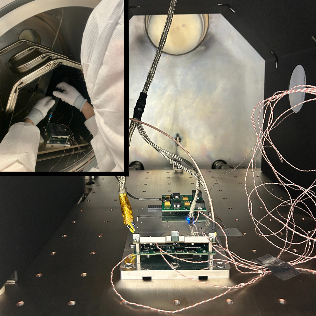
Inside the Thermal Vacuum Chamber
In the subsequent three “operational” cycles, issues arose with both boards.
-
For the OBC board, we identified a misconfiguration of the MCU clock, leading to malfunctions in the CAN bus and MRAM functionality. This issue was resolved by properly adjusting the clock source.
-
As for the Communications board, a hardware problem related to the clock and a resistor, which regulates the voltage supplied to the board, triggered an overvoltage shutdown when it shouldn’t have.
Fortunately, we were able to replace the faulty hardware, ensuring proper operation of both boards during the final “hot and cold” cycle.
Next Steps: Enhancing PeakSat’s Reliability and Performance
Looking ahead, we are committed to further enhancing the reliability and performance of PeakSat’s components. We plan to repeat the Vibration and Thermal Vacuum Chamber tests for these subsystems, incorporating the appropriate improvements identified during the initial testing phase. Additionally, we will conduct a Shock Test to simulate the sudden acceleration that the satellite may experience during its journey towards space.
In parallel, we are preparing to develop a Flat-Sat prototype of PeakSat—a model of our satellite’s subsystems laid out in a flat configuration. This prototype will allow us to verify that all subsystems work seamlessly together before the final assembly.
Looking back, our journey to test and prepare PeakSat’s components for the challenges of space has been more than just a series of technical trials.
No matter the outcome of the campaign tests, we consider them successful because they have provided invaluable insights into the potential malfunctions of the parts, ensuring the resilience and reliability of PeakSat’s components in the harsh realities of space!